
 我他妈说我是个好人
1.1. This standard prescribes a test method for determining the density of smoke emitted by electric wires and cables, during burning, in test conditions defined, and not necessarily the same as those that occur in fires.
1.2. The density of the smoke is an important aspect in analyzing the behavior of electric wires and cables in the presence of fire because it’s directly related to the evacuation of the public reached the site and the access to this for fire fighting.
1.3. The measurement of the density of smoke emitted is based on the signal provided by a photometric system.
1.4. Samples used are made of wires or cables complete in order to bring the test results to real situations.
1.5. This standard allows comparing the behavior of different types of wires or cables, or check if a wire or electric cable meets the requirements of applicable standard.
1.6. This test must be satisfactorily performed, so that the combination of camera and optical system generate consistent results comparing other cameras with identical wires and cables burned under the same conditions.
3. Definitions
3.1. Transmittance
Fraction of light energy that passes through a column of solution.
3.2. Absorbance
Co-logarithm of solution transmittance, optical density.
4. Equipment
4.1. Test chamber
4.1.1 The chamber must have a cubic form, edge (inner side) equal to (3000 ± 30) mm with profiled steel structure, and walls, roof and floor of a suitable material under test conditions. One wall should contain an access door with a glass window for visual inspection. Two other windows sealed transparent, with minimum dimensions of 100 mm x 100 mm must be provided on opposite walls to allow the transmission of a light beam from the horizontal photometric system. The distance from the floor to the center of these two windows should be (2150 ± 100) mm. The chamber walls must have openings at ground level for the passage of control cables and keep the camera at atmospheric pressure. The total area of these holes open during the test shall not exceed (50 ± 10) cm2.
4.1.2. One example of test chamber is shown in Annex A, Figure 1.
4.2. Duct for smoke extraction
The duct must have a valve that can be closed when running the test and may include an exhaust fan to increase the extraction rate at the end of each test. It recommended that the chamber door is opened to allow watching the extraction process.
4.3. Photometric system
The drawing of the photometric system is shown in Annex A, Figure 2.
4.3.1. Light Source
4.3.1.1. The light source should be located outside the chamber, isolated physically and positioned in the center of one of the windows opposite, so that the light beam passes through the chamber windows and it focuses on the photocell receiver.
4.3.1.2. It should consist of a halogen lamp with tungsten filament and clear quartz bulb (transparent), having the following characteristics:
a) nominal power: 100 W;
b) nominal voltage: 12 V;
c) nominal luminous flux: 2000 Lm 3000 to Lm;
d) nominal color temperature: 2800 K to 3200 K.
4.3.1.3. It should be mounted on wrap which light beam is adjusted by a lens system and enables the obtaining of an illuminated circular area with a diameter of (1.5 ± 0.1) m on the inner surface of the wall.
4.3.2. Power supply
The light source should be powered with stabilized voltage (12.00 ± 0.01) VDC.
4.3.3. Photocell receiver
4.3.3.1. The photocell shall be of the selenium or silicon, with response spectrum according to Fotoptic Observer CIE - Commission Internationale de L'Eclairage (equivalent to the human eye).
Note: The definition of Fotoptic Observer is in lEC 50 (845), issued in conjunction with the CIE.
4.3.3.2. It should be mounted on the end of a tube with a length of (150 ± 10) mm, physically isolated from the chamber, with the inner surface painted matt black to prevent reflections. At the other end there should be a transparent protective against dust. The tube should be located outside the chamber, isolated physically and positioned in the center of the window opposite to the source of light.
4.3.3.3. The photocell must be operated with resistive load in order to send an
electrical signal in linear scale and must be connected to a potentiometric recorder.
4.3.4. Potentiometric recorder
The Potentiometric recorder must have input impedance of at least 104 times greater than the resistive load of the photocell, which should not exceed 100 ohms, and must have adjustment of the scale.
4.3.5. Standard Filters of Neutral density
Standard filters must be dimensions enough to cover the entire area of the incident light on the photocell. Standard filters allow you to check the linearity of response of the photocell, which should be proportional to the absorbance of light in the range used.
Note: Neutral density filters are those that do not change the camera, the spectral composition of the luminous flux incident.
4.4. Fuel container
The container should be constructed with sheets of galvanized or stainless steel, with welded edges, forming a truncated pyramid, with dimensions and positioning of Annex A, Figures 3 and 4.
4.5. Fan
To ensure a uniform distribution of smoke, a fan should be placed on the floor of the chamber, as shown in Annex A, Figure 1. The fan shaft shall be 200 mm to 300 mm above floor level and a distance of (500 ± 50) mm from the wall. The fan must have propellers (300 ± 60) mm to provide an airflow of 10 to 15 m3/min in the horizontal direction.
4.6. Cover Plate
The dimensions and positioning of the cover plate are listed in Appendix A, Figure 1. Its objective is to protect the source of fire that direct incidence of air flow.
5. Qualification of equipment
5.1. Photometric system
5.1.1 Periodic verification
Periodically, for example, at the beginning of a series of tests, the performance of the photocell should be checked by placing standard filters and measuring the absorbance. The measured values must be located in a range of ± 5% over the nominal value of the standard filters. The filters also allow you to check the linearity of response of the photocell, which should be proportional to the absorbance of light in the range used.
5.1.2. Setting the limits
Before the test blank, the photometric system and graphic recorder must be energized. It should be a few minutes until stabilization. Next, you must make the adjustment from zero (corresponding to absence of light on the photocell) and the end of the scale of the register (corresponding to 100% of transmitted light).
5.2. Blank Test
5.2.1. Environment
The external environment of chamber should have temperature of (20 ± 10) ° C. A chamber should not be exposed to direct sunlight or severe weather conditions.
5.2.2. Source of fire
It should be composed of (1.00 ± 0.01) L of a mixture with percentages obtained with a pipette and volumetric flask as follows:
- Ethanol (90 ± 1)%
- Methanol (4 ± 1)%
- Water (6 ± 1)%
When a denaturing agent is added to ethanol or methanol, this should not affect the emission of smoke in any wire or cable tested. The mixture should be contained in the fuel container described in 4.4.
5.2.3. Pre-burning
It should be burned 1 liter of the mixture defined in 5.2.2 in order to preheat the camera and ensure that the temperature inside to be (25 ± 5) ° C, measured on the inner
surface of the access door at a height of 1,5 m to 2,0 m and a minimum distance of 200 mm from the walls.
5.2.4. Extraction of smoke
After pre-burning, the chamber must be opened and used the smoke extraction system, described in 4.2, in order to renew the air inside.
5.3. Qualification testing
5.3.1. Cleaning
It must be cleaned the windows of photometric system in order to obtain 100% of light transmission after the stabilization of the voltage.
5.3.2. Fire Source
Should be prepared the following mixtures using pipette and volumetric flask, for greater accuracy, in the following proportions by volume:
a) mixture A: 4% toluene and 96% of the mixture defined in 5.2.2;
b) mixture B: 10% toluene and 90% of the mixture defined in 5.2.2.
5.3.3. Implementation of qualification testing
It should be making two blank tests, using mixtures A and B, respectively. Record the transmission of light. Note, in each case, the value corresponding to the minimum transmittance (LT) occurred during each test. The test is finished when there is no decrease in transmittance for a period of 5 minutes after the end of combustion or 40 minutes after the beginning the burning of the mixture.
5.3.4. Check of Absorbance value
5.3.4.1. Calculation of the absorbance measurement (Am):
Am =log 10 x (Io / It )
Where: Io = Initial Transmitance
5.3.4.2. Calculation of reference absorbance values (Ao):
3 % Toluene Length of ligh beam (m)
5.3.4.3. The calculated values of Ao must be between the following limits:
a) The mixture (4% toluene): 0,18 to 0,26;
b) mixing 8 (10% toluene): 0,80 to 1,20.
Note: In Appendix B, are given some clarification on requirements established in this chapter.
6. Running the test
6.1 Sample
6.1.1 Length and conditioning
The samples hall consist of straight pieces of complete cable with a length of (1.00 ± 0.05) m,
carefully located and conditioned for a minimum of 16 hours (23 ± 5) ° C.
6.1.2. Selection and Mounting of Cables
6.1.2.1. The samples should be selected according to Table 1.
6.1.2.2. The samples should be mounted in parallel without spacing between them. It should be tied together by clamps at 300 mm of the edge. It should be fixed in appropriate support according to Annex A, Figure 4.
6.1.2.3. For Diameter external Cable 3 - D - 10, each beam should consist of seven samples twisted with step of 70 to 10 times the diameter of the beam. It should be tied to each 100 mm from the middle of the beam with two turns of a wire 0.5 mm in diameter. The beams must be mounted according to 6.1.2.2.
6.2 Positioning the fuel container and samples
6.2.1. The fuel container shall be located above the floor to allow air circulation, according to Annex A, Figure 4.
6.2.2. The samples should be positioned horizontally above the container so that the distance between the bottom surface of the samples and the base of the container is (150 ± 5) mm, according to Annex A, Figure 4.
6.3. Test Procedure
6.3.1. The external environment of chamber should be temperature (20 ± 10) ° C The temperature inside the chamber to the start of the tests should be in the range (25 ± 5) ° C. Before each test or series of them, should be performed a blank test as 5.2.
6.3.2. After each test, the windows of the photometric system should be cleaned to regain l00% of light transmission after the stabilization of the voltage.
6.3.3. With the samples installed on the tray, it must be opened for air circulation and burning the mixture. The test chamber shall be evacuated immediately and the door should be closed.
6.3.4. The test is completed when there is no decrease in transmittance for a period of 5 minutes after the end of combustion or 40 minutes after the start of the burning mixture.
6.3.5. You should register the minimum transmittance and extract the product from the burning after end of each test.
7. Results
7.1. The evaluation of test results should be made based on the minimum
transmittance specified by the standard applicable to the wire or cable.
7.2. When it is not specified one applicable standard, but it is required low emission of smoke, the minimum transmittance should be as shown in Table 2.
Table 2 - Minimum Transmittance
ANNEX A - DRAWINGS
Figure 1 - Plan view of the test chamber
Unit: mm
Unit: mm
Unit: mm
Unit: mm
Annex B - Information on the test procedure
B-1. The chamber and the environment
B-1.1. The qualification test, according to 5, makes it unnecessary to specify the
thickness of the wall of the chamber in order to ensure uniform heat dissipation. Have been used steel walls and ceilings of about 2 mm thick.
B-1.2. It is important to ensure the equalization of pressure according to 4.1. B-1.3. The condensation of moisture from the air inside of chamber can cause
anomalous results. For exampIe,15 ° C is unacceptable, 18 ° C is the minimum, and 20 ° C is the minimum safe value.
B-1.4. The metal container containing the mixture of toluene should be located above the floor to allow air circulation.
B-2. Optic System
B-2.1. It is not necessary to check the output intensity of the light source, since the accuracy of test results independent of the power effectively dissipated by bulbs, which can be operated up to fail.
All measures of It are referred to initial value Io.
B-2.2. The effect of color temperature and emissivity of the bulbs at various
wavelengths can be considered negligible, since the receiving system depends on the perception of the human eye. In short, the loss of intensity in the "blue end", or gain intensity in the "red end" of the spectrum, normal aging process of the bulbs, it is irrelevant because these wavelengths contribute very little in the evaluation of the receiver.
B-2.3. The effects mentioned in the previous sections allow us to conclude that it is of little importance to accuracy of the initial value of the dc voltage applied to the bulb. In fact, if a voltage of 12,1 V or 11,9 V is applied, instead of 12,0 V, simply changes occur in the absolute intensity and color temperature. These two effects practically do not influence the results. The most important aspect is that the applied voltage must be kept stable around a small tolerance. Thus, the ideal is that the voltage variation is maintained within ± 0,01 V throughout the test.
B-2.4. The specified photoelectric cell operates with guarantee in its linear range. Note: For example, the cell type of selenium MEGATRON ME 45 " becomes a non-linear for output voltage of 40 mV. The voltage value effective observed in the lighting conditions provided in the test chamber is approximately 3.5 mV.
B-2.5. The neutral density filters are necessary to ensure the relative response of the system is maintained uniform over time, observed periodically through evaluation, for example, every month.
B-2.6. The nature of relation Io/It indicates that, theoretically, there is no need to clean the windows of the optical system before use. However, in practice, there is a need to
make cleaning due to reflection in the window detector vary considerably with small amounts of smoke deposited. It’s possible occurs more light transmission after the deposition of some smoke due to reduced quality of the reflective surface. Therefore, cleaning the windows ensures greater consistency in the results.
B-2.7. The light source is adjusted to produce an area of diffuse light and unfocused, in order to allow that photocell is covered by a small portion of an area wide and evenly illuminated. This prevents, for example, the situation in which a bright spot from outside the catchment area of the photocell can, during the formation of smoke, generate light ray, thus producing extra effect in the cell, and cause a false reading.
金属密度
常用金
密度,克/ 密度,克/ 材料名称 材料名
白口铸铁 7.4~7.7 锈 2Cr13Ni4Mn9 8.5
钢 可锻铸铁 7.2~7.4 3Cr13Ni7Si2 8.0 铸 7.8 纯铜材 8.9 工业纯铁 7.87 59、62、65、68黄铜 8.5 普通碳素钢 7.85 80、85、90铜 8.7 优质素钢 7.85 96黄铜 8.8 碳素工具钢 7.85 59-1、63-3铅黄铜 8.5 切钢 7.85 74-3铅黄铜 8.7 锰钢 7.81 90-1锡黄铜 8.8 15CrA铬钢 7.74 70-1锡黄铜 8.54 20Cr、30Cr、40Cr铬钢 7.82 60-1和62-1锡黄铜 8.5 38CrA钢 7.80 77-2铝黄铜 8.6 铬钒、铬镍、铬镍、铬锰、 67-2.5、66-6-3-2、60-1-1铝黄铜 8.5 7.85 硅、铬锰硅镍、锰、硅铬钢 镍黄铜 8.5 铬钨钢 7.80 锰黄铜 8.5 铬钼铝钢 7.65 硅黄铜、镍黄铜、铁黄铜 8.5 含钨9高速工具钢 8.3 5-5-5铸锡青铜 8.8 含钨18高速工钢 8.7 3-12-5铸锡青铜 8.69 强度合金钢` 7.82 6-6-3青铜 8.82 轴钢 7.81 7-0.2、6.5-0.4、6.5-0.1、4-3锡
0Cr13、1Cr13、2Cr13、3Cr13、
4Cr13、Cr17Ni2、Cr18、9Cr18、7.75 4-0.3、4-4-4锡青铜 8.9 不 Cr25、Cr28
Cr14、Cr17 7.7 4-4-2.5锡青
1Cr18Ni11Si4A1Ti 7.52 LD8 2.77 锻
铝 7铝青铜 7.8 LD7、LD9、LD10 2.8 19-2铝青 7.6 超硬 2.85 9-4、10-3-1.5铝青
变 3-1硅青铜 8.47 MB2、MB8 1.78 形 1-3硅青铜 8.6 MB3 1.79 镁 1铍
0.5镉青铜 8.9 铸镁 1.8 0.5铬青铜 8.9 工业纯钛(TA1、 TA2、 TA3) 4.5 1.5锰青铜 8.8 TA4、TA5、TC6 4.45 5锰青铜 8.6 TA6 4.4
B5、B19、B30、BMn40-1.5 8.9 TA7、TC5 4.46 钛
BMn3-12 8.4 TA8 4.56
BA113-3 8.5 TC3、TC4 4.43
纯铝 2.7 TC7 4.4
金 LF2、LF43 2.68 TC8 4.48
LF3 2.67 TC9 4.52 防
锈 LF5、LF10、LF11 2.65 TC10 4.53 铝 LF6 2.64 纯镍、
LF21 2.73 镍铜、镍镁、
LY1、LY2、LY4、LY6 2.76 镍铬合金 8.72
LY3 2.73 锌锭(Zn0.1、Zn1、Zn2、Zn3) 7.15 硬 LY7、LY8、LY10、LY11、LY14 2.8 铸
LY16、LY17 2.84 4-0.5
LD2、LD30 2.7 铅和铅合金 11.37 锻 LD4 2.65
_金属密度
密度表
常用金属材料密度表,包括黑色、有色金属
材料名称
灰口铸铁白口铸铁可锻铸铁钢工业纯铁普通碳素钢优质碳素钢素具钢易
20Cr、30Cr、40Cr
铬钒、铬镍、铬镍钼、铬锰、硅、铬锰镍、硅锰、硅铬钢铬镍钨钢钼铝含钨9高工钢含钨18
0Cr13、1Cr13、2Cr13、3Cr13、4Cr13、Cr17Ni2、Cr18、9Cr18、Cr25、Cr28不锈钢
Cr14、Cr17
0Cr18Ni9、1Cr18Ni9、Cr18Ni9Ti、2Cr18Ni91Cr18Ni11Si4A1Ti7铝青铜19-2铝青铜
9-4、10-3-1.5铝青铜10-4-4铝青铜铍青铜3-1硅青铜1-3青铜1铍
B5、B19、B30、BMn40-1.5BMn3-12白铜
BZN15-20BA16-1.5
密度克/厘米
3
材料名称
不锈钢
1Crl8NillNb、Cr23Ni182Cr13Ni4Mn93Cr13Ni7Si2
密度克/厘米
3
6.6~7.47.4~7.77.2~7.4
纯铜材
、62、65、68黄铜、85、90黄铜黄铜
、63-3铅黄铜黄铜锡黄铜锡黄铜
67-2.5、66-6-3-2、60-1-1铝黄铜镍黄铜锰黄铜
硅黄铜、镍黄、铁黄铜铸锡青
、6.5-0.4、6.5-0.1、4-3锡青铜、4-4-4锡
LD8
LD7、LD9、LD10
超硬铝
工业纯钛(TA1、TA2、TA3)钛合金
TA4、TA5、TC6TA6TA7、TC5TA8TB1、TB2TC1、TC2
变形镁
MB1MB2、MB8MB3
MB5、MB6、MB7、MB15
材料名称
BA113-3纯铝
LF2、LF43防锈铝
LF3
LF5、LF10、LF11LF6LF21
LY1、LY2、LY4、LY6LY3硬铝
LY7、LY8、LY10、LY11、LY14LY9、LY12LY16、LY17LD2、LD30锻铝
LD4LD5
密度克/厘米
3
材料名称
TC3、TC4TC7
钛合金
TC8TC9TC10
密度克/厘米
3
纯镍、阳极镍、真空镍镍铜、镍
锌锭(Zn0.1、Zn1、Zn2、Zn3)铸锌
铸造锌铝合金造锌铝合金铅
金属密度
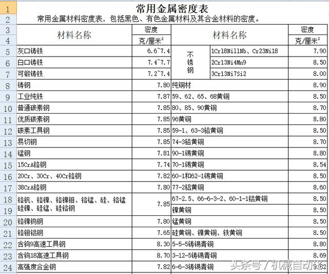
常用金属材料密度表
常用金属材料密度表,包括黑色、有色金属材料及其合金材的密度。材料
克/厘米3
灰口铸铁6.6~7.4不锈钢1Crl8NillNb、Cr23Ni187.9
白口铸铁7.4~7.72Cr13Ni4Mn98.5
可锻铸铁7.2~7.43Cr13Ni7Si28.0
铸钢7.8纯铜材8.9
工业纯铁7.8759、62、65、68黄铜8.5
普通碳素钢7.8580、85、90黄铜8.7
优质碳素
碳素工具钢7.8559-1、63-3铅黄铜8.5
易切钢7.8574-3铅黄铜8.7
锰钢7.8190-1锡黄铜8.8
15CrA铬
20Cr、30Cr、40Cr铬钢7.8260-1和62-1锡黄铜8.5
38CrA铬
铬钒、铬
铬锰硅镍、硅锰、硅铬钢7.8567-2.5、66-6-3-2、60-1-1铝黄铜8.5
镍黄铜8.5
铬镍钨钢7.80锰黄铜8.5
铬钼铝钢7.65硅黄铜、镍
含钨9高速工
含钨18高速
8.69
高强度合金钢7.826-6-3铸锡青铜8.82
轴承钢7.817-0.2、6.5-0.4、6.5-0.1、4-3锡青铜8.8
不锈钢
0Cr13、1Cr13、2Cr13、3Cr13、4Cr13、
Cr17Ni2、Cr18、9Cr18、Cr25、Cr287.754-0.3、4-4-4锡青铜8.9
Cr14、Cr177.74-4-2.5锡青铜8.75
0Cr18Ni9、1Cr18Ni9、Cr18Ni9Ti、
2Cr18Ni97.855铝青铜8.2
1Cr18Ni11Si4A1Ti7.52锻铝LD82.77
7铝青铜7.8LD7、LD9、LD102.8
19-2铝
9-4、10-3-1.5铝青铜7.5LT1特殊铝2.75
10-4-4青铜7.46
铍青铜8.3变形镁MB11.76
3-1硅青铜8.47MB2、MB81.78
1-3硅
1铍青铜8.8MB5、MB6、MB7、MB151.8
0.5镉
0.5铬青铜8.9工业纯钛(TA1、TA2、TA3)
4.5
1.5锰青铜8.8钛合金TA4、TA5、TC64.45
5锰青铜8.6TA64.4
白铜B5、B19、B30、BMn40-1.58.9TA7、TC54.46
BMn3-128.4TA84.56
BZN15-208.6TB1、TB24.89
BA16-1.58.7TC1、TC24.55
BA113-38.5TC3、TC44.43
纯铝2.7TC74.4
防锈铝LF2、LF432.68TC84.48
LF32.67TC94.52
LF5、LF10、LF112.65TC104.53
LF62.64纯镍、阳极镍、电真空镍8.85
LF212.73镍铜、镍镁、镍硅合金8.85
硬铝LY1、LY2、LY4、LY62.76镍铬合金8.72
LY32.73锌
7.15
LY7、LY8、LY10、LY11、LY142.8铸锌
6.86
LY9、LY122.784-1
LY16、LY172.844-0.5铸造锌铝合金6.75
锻铝LD2、LD302.7铅和
LD42.65铅阳极板11.33
LD52.75
力学测试之金属标准
Chatillon 网站
以下我们所列出的准的全部细节可从授权
ASTM International -ASTM 国际标准组织
British Standards Institute BS -BS
International Organisation for Standardization ISO -国际标准化组织ISO -
European Committee for Standardization EN -会EN
International Electrotechnical Commission IEC -国际电工委员会(IEC )-
Test Standards -Metals 测试标准-金属
以下是
ASTM B598ASTM B598本练习包含测定的屈服度(0.01%,0.02%,和0.05%的偏量),温下。它是用于合金气通常用于弹簧应用
ASTM E1012ASTM E1012该测试方法用于测定硬质的承载强
ASTM E209ASTM E209这种做法涵盖了程序,设备非金属材料的压缩试验标本。ASTM E21ASTM E21些试验方法包括序和仪的测定拉伸强度,屈服
ASTM E238ASTM E238这种测试方法涵盖了金材料的针型轴验,以确定
ASTM E292ASTM E292这测试方法涵盖的时间恒定负载和温条件,缺口试样裂决心。这些测
ASTM E345ASTM E345这些测试方法覆盖金属箔的度小0.006英
ASTM E8ASTM E8具体地,在这试验方法包括任何形式的金属材料室温下的拉伸试方法,测定屈服强度,服点伸长率,拉伸强度,伸长率收缩率。ASTM E9ASTM E9这些测试方覆盖
BS 4A 4-1.2:1967BS 4A 4-1.2:1967金属材料试片的试验
公制单位:
BS 4A 4-1.3:1967BS 4A 4-1.3:1967金属材料的试验片试验
Metric units. 公制单位。
BS EN 10002-1:2001BS EN 10002-1:2001属料的拉伸
BS EN 10002-5:1992BS EN 10002-5:1992金料的拉伸试
BS EN 10319-1:2003BS EN 10319-1:2003属材料拉伸
BS EN 13523-7:2001BS EN 13523-7:2001线圈涂层
试验)。
BS EN 23312:1993,ISO 3312:1987BS EN 23312:1993,ISO 3312:1987
BS EN 23327:1993,ISO 3327:1982BS EN 23327:1993,ISO 3327:1982硬质合金横向断裂强度的测定。
BS EN ISO 7438:2000BS EN ISO 7438:2000金属材料弯曲试验。
BS EN ISO 7500-1:2004BS EN ISO 7500-1:2004金
拉伸/压缩
BS EN ISO 7622-2:1996BS EN ISO 7622-2:1996钢丝绳芯输送带向牵试
BS EN ISO 8491:2004BS EN ISO 8491:2004金属材料弯曲试验。
BS EN ISO 8496:2004BS EN ISO 8496:2004金属材料环拉伸试验。
--------------------------------------------------------------------------------
EN ISO 7438EN ISO 7438金属材料弯曲试验。
ISO 10113ISO 10113金属材料
ISO 10447ISO 10447电焊接电阻点焊和凸焊的剥离和凿子
ISO 3327ISO 3327硬质合
不尽之处,随时联系笔者
转载请注明出处范文大全网 » NBR11300烟密度测试标准

